27.11.11

Extruder Experimentation


My working theory is that there is a pause in extrusion which leads to a cool down and hence a jam when the motor can't start up again.

Another theory is there is a deflection in the filament within the Bowden cable - and hence stored extrusion pressure - that causes an excessive force to be needed .

Bowden Joint

First, lets see what we can do about the joint between the Bowden tube and the extruder housing. The very nice people at Norgren have the specification for the NSF-51 connector, and within it are assembly instructions. I hope they don't mind if I post them here.
Norgren PNEUFIT® D Assembly Instructions
Using those instructions (i.e. cutting off the 10mm of chewed up Bowden cable, and sinking it past the O-ring) the gap is reduced to about 0.8mm.
End of Bowden Tube.
After Reassembly
While Extruding

That's still not good, because of the play in the tube; ±0.8mm is 5.4mm³ of plastic, but I feel better about it.

However, it doesn't solve the problem and the extrusion still stops mid-print. I also noticed that the gap returns to more than a millimeter while extruding.

26.11.11

Extruder Issues

I'm having issues with the extruder. The symptom is that the extrusion stops after the first layer (or so) because the hobbed bolt of the extruder has worn the filament away and it can't get a grip on it. The picture below shows two locations where the normal grip zipper pattern is interrupted by a worn spot.
Worn spots on the filament where the hobbed bolt has ground it away.
So, how to debug this problem?
Another effective technique is to explain your code to someone else.  This will often cause you to explain the bug to yourself. Sometimes it takes no more than a few sentences, followed by an embarrassed "Never mind, I see what's wrong.  Sorry to bother you."  This works remarkably well; you can even use non-programmers as listeners.  One university computer center kept a teddy bear near the help desk.  Students with mysterious bugs were required to explain them to the bear before they could speak to a human counselor.  ~Brian Kernighan and Rob Pike, about debugging
Here are some data points by way of explaining it to the teddy bear...

Temperature Deviation

After a suitable amount of time for the control system to stabilize, the extrusion head is running about 11° colder than the set point temperature when the cooling fan is enabled and 5° colder when the fan is off - at least according to the Control Panel of ReplicatorG:

Extrusion Head Temperature Deviation
Target Fan
On
Fan
Off
240.0°229°236°
245.0°234°240°
250.0°239°245°

Bowden Cable Loose

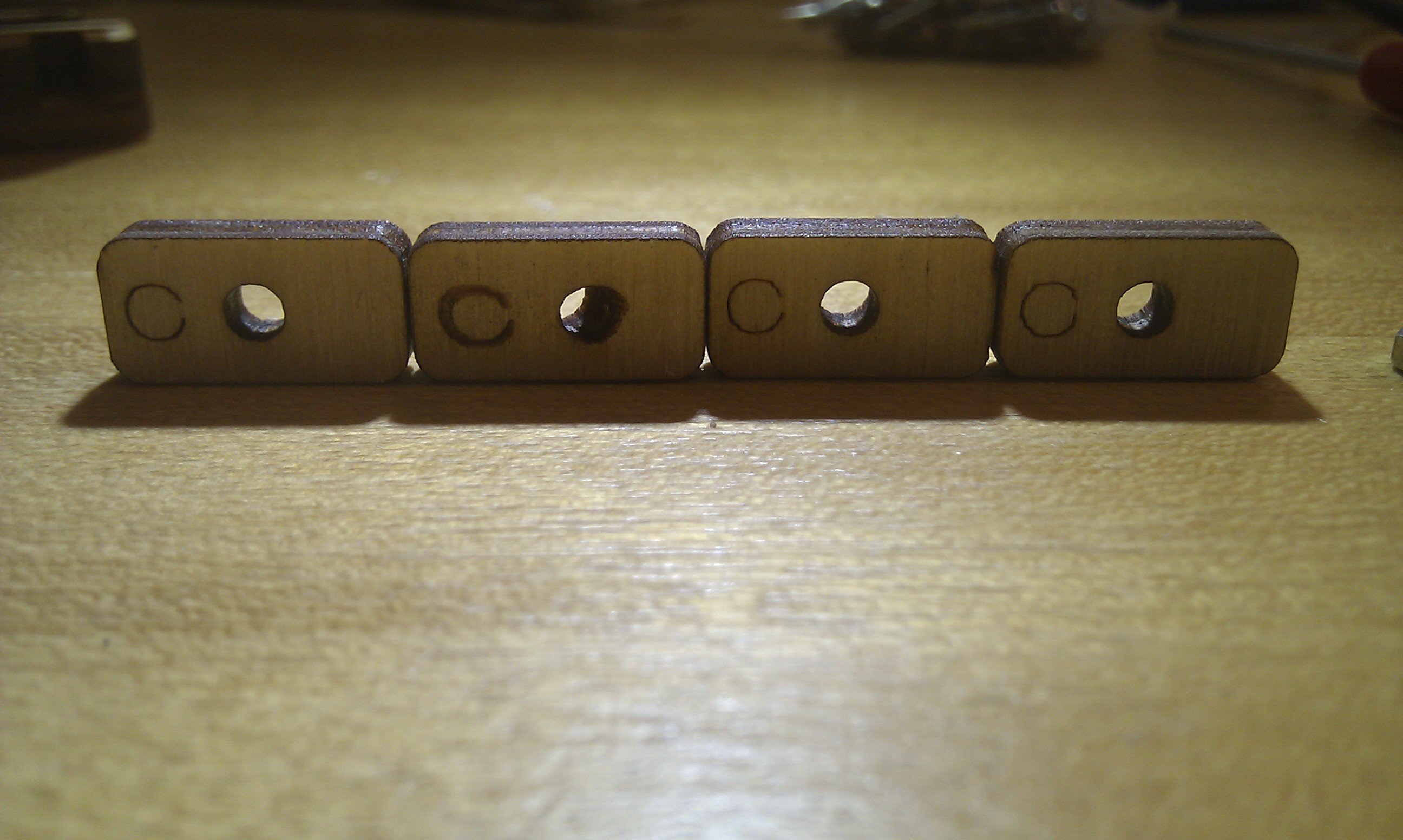
The Bowden cable is loose on the extruder. There's about a 1.1mm gap between the collar of the retaining ring and the plastic adapter piece. This gap can increase to 1.8mm if you pull up on the retaining ring, but then the gap isn't equal all the way around it; the other side gap reduces to 0.9mm or so.
Bowden tube attachment gap.
The assembly instructions didn't include anything about how to attach the Bowden cable to the extruder, so I just put the retaining ring on it and jammed it in. That may be the problem. How to tighten it up though?

Starting & Stopping

Using the ReplicatorG Control Panel to extrude by clicking the Motor Control 'forward' radio button when the head is up to temperature, there is about a 4 or 5 second lag before plastic starts to come out.

The extruder motor control via the Control Panel is really flakey though. There is a long lag between stopping extruding by clicking the Motor Control 'stop' radio button and when the motor actually stops turning. The longer you leave the extruder running, the longer it takes the motor to turn off when you do click 'stop'.

But, after the extruder motor really does stop, there continues to be plastic extruded for about 10 to 15 seconds afterwards. This amounts to about 7cm of extruded plastic. If this is 0.4mm diameter extrusion (it measures pretty close to that) like the nozzle says it should be, then 70mm of extra extrusion is about 8.8mm³ of plastic. This corresponds to an input length of ⌀2.94mm filament approximately 1.3mm long.

Extrusion Rate

The extruder hobbed bolt rotates at approximately 1 rpm (58 seconds for a complete revolution) when the Motor Speed (RPM) [sic] is set to 1500. When the  "drive gear" in Skeinforge is set to 6.5mm diameter, 1 rpm corresponds to a radial speed of 20.4mm/min or 0.34mm/sec.
Note: At 200 steps per revolution and the gear ratio of 8:49 in the extruder, the stepper is stepping 1,288 per minute, so the 1500 number seems to be completely bogus. But the motion seems to be a series of bursts of steps with pauses in between so this may represent a target stepping rate. This is probably a firmware issue, where there is only a "subroutine" to step so-many steps, and not a continuous run subroutine.

G Code Value

What do the extruder G code units correspond to? Looking in the .gcode file, after running a part, the absolute position of the extruder is E18151.976 with 100% fill. From the Inventor iProperties for that part, the volume is 1597.773 mm³, so that's about 0.088 mm/unit. Thus, the start.txt code of E260 would extrude 22.9mm³ of plastic or a stream about 18cm long. I guess it's that long.

Motor Speed

When starting the part with the E260 G code, the extruder gear turns not quite 70 degrees in 15 seconds, so approximately 4mm of filament, or 27mm³ of plastic, for an extrusion length of 21cm. I guess that's close enough to 18cm.

20.11.11

Z Axis Calibration - The Movie

After implementing the Z-Axis limit switch fix from GeneralRuleOfDumb, it becomes possible to repeatably trigger the switch, so this is the calibration video.

14.11.11

Support

I read Dave Durant's Blog about Skeinforge Support and thought I would give it a try too, since the first attempt at the HTC Tripod Mount failed badly when trying to draw plastic on thin air.

The biggest trick is to enable the Raft module (code, pass, thingy) without making an actual raft as a base. This mans that the gcode generation is still "raftless" but you need to go into the raft dialog and enable Raft. Then the parameters are like Dave's blog describes.

The effect is to make a footprint that is equal to the shadow cast by a light directly overhead. The footprint is then extended upwards to touch the object. In the HTC Tripod Mount, the base is a square, and the footprint of the overhanging wings makes a couple of pillows to left and right as seen in this image.

Printing with Support.
But another problem reared it's head, the extruder drive is slipping on the plastic material. This leads to a very bubbly looking piece of plastic. You can see the first start in the foreground of the picture. I had to kill it because the plastic wasn't extruding.

I guess I should do the calibration procedure for the extruder feed. But what is that? The only ones I've seen are for the DC motor driven extruders (set the Motor Speed (PWM) between 0 to 255), and the Ultimaker has a stepper driven extruder.

12.11.11

Z Axis Limit Switch

In order to determine when I've succeeded in reworking the Z Axis Limit Switch, I first run a calibration with the existing configuration and measure it.

First we make the bed conductive, by pressing a sheet of aluminum foil onto a dampened bed with a wet paintbrush. I suppose you could use a wet paper towel just as well.

Then we make the tip of the extruder conductive. I would have thought it was, being metal and all, but preliminary tests showed that some plastic had covered the tip from a prior build. So we wipe the extruder nozzle well with a paper towel with acetone on it. Test that the plastic is off by checking for continuity when a flat object like a screw driver blade is brought up to touch the very tip of the extruder nozzle. The metal shield around the heater wires is grounded, so you can clip an alligator clip to that.

Then we set up a digital multimeter as an audible continuity meter and fire up the machine panel of the ReplicatorG software.

By jogging the Z axis, measuring continuity and playing with the adjustment screws of the limit switch, you can get the switch to trip at the same time as the continuity meter indicates the extruder is touching the bed.

It turns out that the mechanical switch has about 0.4 mm of hysteresis. That is, the switch closes at position 0, but you need to back it off to 0.4mm before the switch opens again (see the video for an explanation).

6.11.11

First Plastic

Woo hoo!
The 0.5mm-thin-wall from Thingiverse.

I worked on it most of Saturday, and by about 22:00 I had extruded my first plastic - a small rectangle of PLA. As expected, there's a long way to go.

One of the trickiest parts is the zero of the Z axis - the vertical table movement. It's a left handed coordinate system, so if you're thumb points along positive X and you're index finger points along positive Y, then your middle finger points along positive Z.

Ideally one would like to have the zero point for the Z axis exactly when the platform is touching the extrusion head - and obviously, one would like to have the platform bed perpendicular to the Z axis as well. Both of these are difficult to achieve with any accuracy.

The process for getting the platform perpendicular is to
  • move the head to one corner
  • jog the Z until one can just slide a thickness gauge (a piece of scrap wood) under the head
  • move the head to another corner
  • adjust the level screw for that corner until the one can just slide the thickness gauge under it
  • repeat the above two steps for the other corners
The process for zeroing the Z axis is to
  • jog the Z axis until the platform is touching the head
  • adjust the limit switch position so that it is just triggered at that point
  • move the platform down
  • repeat the above three steps until the triggering of the limit switch coincides with the platform touching the head
First, one needs a fine adjustment control for the upper Z axis limit switch. The way it's adjusted currently is with the two mounting screws in slotted holes.

Second, one needs a calibration procedure that doesn't involve judgment calls on whether a thickness gauge has the same amount of friction as a previous time.

5.11.11

Well In

I've been steadily progressing in the building of the Ultimaker. I found that the rocking I spoke of in the previous post was due to the table I had it on. Placed on the floor, everything is fine. The table is one of those interlocking home-made tables you can make out of one piece of plywood. I have two. Had 'em for years. Maybe it's time to upgrade to less "student" looking furniture.

One of these pieces is not like the other.
Someone was too quick loading/unloading the laser cutter.
So far the motors, X-Y axes and extrusion head are installed. Next up is the Z stage. It's going together quite easily. The only issues so far have been with some small clearances, and a laser cut part that had a diagonal hole because the operator of the laser cutting machine was loading or unloading the birch plywood into the machine while it was cutting (see right).

I need to come up with a title for this blog - "Working Title" isn't cutting it. Maybe a play on words around 3D printing or plastic. But I don't want to limit the blog to just the 3D printer part, when the actual objects being made are the important part. I don't really want to associate myself with the Make or Maker terminology. I feel that Make Magazine and the Maker Shed has subverted the actual Do-It-Yourself/Home-Made movement with a monetization that is the antithesis of the ideals it stands for. Nothing against O'Reilly. It's just that paying for the ideas and plans one "makes" gives me that "ew" feeling.

I would like to work curmudgeon in the title somewhere. Lets call it "The Creative Curmudgeon". No, sorry, that's been taken - twice. OK, how about the "Homemade Curmudgeon". No, that sounds like Suzy Homemaker. How about the "Constructive Curmudgeon". No, taken. "The Curmudgeon Constructs". Hmmm. That works. Done. At least for now.

2.11.11

Construction Start

The Ultimaker arrived today, so naturally I started building the kit.
 
Frame construction.
The first step is the frame construction. I took the time to sand the edges a bit, not that it really needed it, but it leaves a nice smell of birch wood in the air.

There were a few steps where the orientation wasn't clear, so I edited the wiki to (hopefully) clarify it. I love wikis.

One side was tight, so I had to coax it a little with a hammer. Nothing major, just some taps to seat the tabs in the holes.

The one thing that bothers me at this point is that the frame doesn't rest on all four feet, but rocks back and forth a bit. I guess I'll have to loosen all the screws holding it together and change the trapezoidal shape into a rectangular one by using brute strength and measuring with a square. The T-slots are not much smaller than the holes for the nuts, and the wood is kind of soft, so you can't really reef the nuts tight. I wonder if they will hold it square after an adjustment.